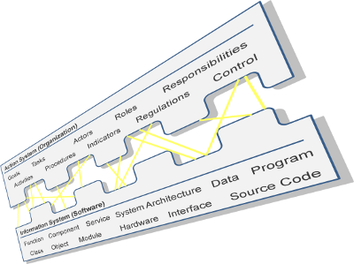
|
Fig. 1
|
Action system and information system as interwoven human-task-technology system
|
|
Fig. 2
|
Business process model of an online order process
|
|
Fig. 3
|
Organization model according to the example process
|
|
Fig. 4
|
Allocation models according to the business process-steps and resources
|
|
Fig. 5
|
Architecture of a Java Server Pages (JSP) based application as generation target for the example
|
|
Fig. 6
|
Mapping model with links to elements from the conceptual model and the implementation strategy model
|
|
Fig. 7
|
Code generation templates of the example project inside editor application
|
|
Fig. 8
|
Graphical user interface of the developed software application
|
|
Fig. 9
|
Meta-meta-model, meta-model, and model instance levels, with example model types used in the presented method
|
|
Fig. 10
|
Relationships between modeling languages, model instances, model transformation specification languages, model transformation specifications and model transformations
|
|
Fig. 11
|
Model-transformation-pattern
|
|
Fig. 12
|
Conceptual business process model versus implementation-oriented executable workflow model
|
|
Fig. 13
|
Relationship between process type declaration and process instances, with information from process logs for an ex-post representation of process instances
|
|
Fig. 14
|
Basic architectural pattern of a self-referential enterprise system
|
|
Fig. 15
|
Steps performed when applying the method
|
|
Fig. 16
|
Entire meta-model for internal enterprise model representation
|
|
Fig. 17
|
Abstract superclasses defining common attributes of elements
|
|
Fig. 18
|
Meta-constructs to model the actor perspective
|
|
Fig. 19
|
Meta-constructs to model the process perspective
|
|
Fig. 20
|
Meta-constructs to model the resource perspective
|
|
Fig. 21
|
Pattern of a single mapping association
|
|
Fig. 22
|
Excerpt of the mapping meta-model showing the use of implementation strategy models
|
|
Fig. 23
|
Entire meta-model specifying the core concepts of the mapping model language
|
|
Fig. 24
|
Implementation strategy specification in a mapping model editor, using dynamic parameter resolving
|
|
Fig. 25
|
Overall methodical procedure
|
|
Fig. 26
|
Software development using the configured method
|
|
Fig. 27
|
Create and edit enterprise models
|
|
Fig. 28
|
Cycle of editing, transforming, and checking conceptual models
|
|
Fig. 29
|
Process of manually editing the mapping model
|
|
Fig. 30
|
Cycle of initializing or updating a mapping model, manually revising it, and automatically checking its validity
|
|
Fig. 31
|
Generate deployable artifacts
|
|
Fig. 32
|
Taking the decision to adapt the method to a set of enterprise modeling languages
|
|
Fig. 33
|
Sub-process to adapt the method to a set of enterprise modeling languages
|
|
Fig. 34
|
Enriching an enterprise model with additional semantics via a comment text hint
|
|
Fig. 35
|
Taking the decision to adapt the method to a new target architecture
|
|
Fig. 36
|
Sub-process to adapt the method to a new target architecture
|
|
Fig. 37
|
Distributed components in a client-server architecture
|
|
Fig. 38
|
Schematic sketch of an abstract user interface with generic interaction functionality for an EIS front-end
|
|
Fig. 39
|
API interfaces to implement EIS functionality
|
|
Fig. 40
|
Front-end API interfaces for distributed EIS applications
|
|
Fig. 41
|
Back-end API interfaces for a central coordination server for distributed EIS applications
|
|
Fig. 42
|
Entire meta-model specifying platform-independent implementation strategies for process-members
|
|
Fig. 43
|
Meta-model excerpt specifying platform-independent user decision implementation strategies
|
|
Fig. 44
|
Meta-model excerpts specifying more platform-independent user interaction implementation strategies
|
|
Fig. 45
|
Meta-model excerpt specifying platform-independent high-level process-steps
|
|
Fig. 46
|
Meta-model excerpt specifying platform-independent automatic process-steps
|
|
Fig. 47
|
Meta-model excerpt specifying platform-independent event implementation strategies
|
|
Fig. 48
|
Meta-model specifying platform-independent control flow implementation strategies
|
|
Fig. 49
|
Meta-model excerpt specifying platform-independent implementation strategies for actor resolvers
|
|
Fig. 50
|
Meta-model specifying platform-independent implementation strategies for conditions
|
|
Fig. 51
|
Meta-model excerpt specifying platform-independent implementation strategies for actors
|
|
Fig. 52
|
Meta-model excerpt specifying platform-independent information types
|
|
Fig. 53
|
Meta-model excerpt specifying platform-independent information storage implementation strategies
|
|
Fig. 54
|
Meta-model excerpt specifying platform-independent software resource implementation strategies
|
|
Fig. 55
|
Meta-model excerpt specifying the physical resource implementation strategy
|
|
Fig. 56
|
Meta-model excerpt showing the basic pattern of an AbstractProcessMemberImplementation strategy referencing resource source and resource target accesses
|
|
Fig. 57
|
Meta-model excerpt specifying platform-independent storable information object access implementation strategies
|
|
Fig. 58
|
Entire meta-model specifying platform-independent implementation strategies for resources
|
|
Fig. 59
|
Excerpt of an example food supply chain model in a domain-specific modeling language
|
|
Fig. 60
|
Conceptualizations of the distributed architecture, a) original peer-to-peer setting, b) using ESB proxies to securely interconnect existing legacy systems
|
|
Fig. 61
|
Core concepts of the implementation strategy meta-model for describing a SOA environment
|
|
Fig. 62
|
Entire implementation strategy meta-model for describing the example SOA target architecture
|
|
Fig. 63
|
Example implementation strategy model instance in the language defined by the implementation strategy meta-model
|
|
Fig. 64
|
Excerpt of a visual representation of the generated executable BPEL workflow model
|
|
Fig. 65
|
Excerpt of a graphical model representation of the generated WSDL interface declaration for the BPEL process
|
|
Fig. 66
|
Overview on the implemented example method components and steps
|
|
Fig. 67
|
Excerpt from a MEMO process control flow model referencing elements from other perspectives
|
|
Fig. 68
|
Example implementation strategy meta-model for a web application architecture
|
|
Fig. 69
|
Enterprise model editors in MEMOCenterNG
|
|
Fig. 70
|
Mapping model tree structure editor, with references to separate model instances
|
|
Fig. 71
|
Editors for Xtend and Xpand scripts in the development environment
|
|
Fig. 72
|
Built-in menu functionality in the Eclipse environment to invoke transformations and validity checks of the method
|
|
Fig. 73
|
Menu and toolbar in the Eclipse environment to invoke transformations and validity checks in the method
|
|
Fig. 74
|
Model editors for the internal EEM representation of enterprise models
|
Figures which are reproduced as smaller excerpts of larger images in the book are available here in full-size.